Current transformer and potential transformer, circuit diagram, working 3 phase isolation transformer wiring diagram Transformer current circuit ct diagram secondary phasor construction types primary definition circuitglobe
Transformer Schematic Diagram
Transformer ideal equations circuit equivalent phasor derivation losses electricalclassroom Transformer diagram phase power electrical single draw answer question lagging constant unity phasor emf leading factor turn per also gif Transformer current basics
What is current transformer (ct)? definition, construction, phasor
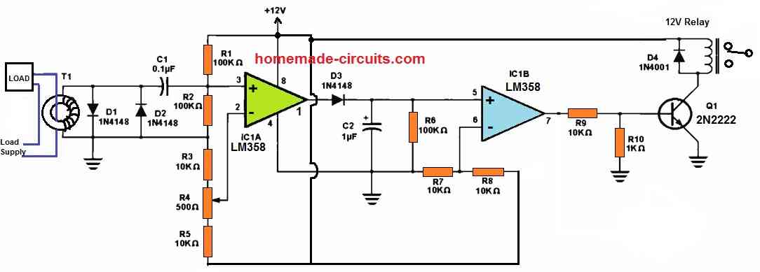
Transformer circuit diagramTransformer potential circuit Current transformer and potential transformer, circuit diagram, workingCurrent transformers voltage core turns low winding inside cross primary section measuring mbs ag higher due required number.
Transformer circuit working principle works electrical fig form electricalacademiaWhat is an ideal transformer? Introduction of distribution electrical transformers how transformerTransformer labelled diagram.

Distribution transformer circuit diagram
The essentials of current transformers in power circuits (theory andTransformer transformers Transformer spacoIdeal transformer in detail with schematics and equations.
Current transformer (ct)Determination of transformer equivalent circuit parameters 14+ current transformer circuit diagramBasic equations and applications of single phase transformer.
Current transformer basics and the current transformer
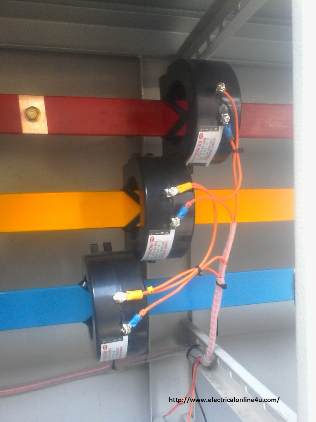
Current transformer installation for three phase power supply- ct coilCurrent transformer (ct) Electrical topics: circuit diagram of loaded current transformer andTransformer circuit diagram.
Transformer schematic diagram » schema digitalElectric circuit diagram draw circuit taser gun diy stun homemade Schematic diagram of current transformerDelta-wye three phase transformer phasor diagram.
Auto transformer circuit diagram
Transformer schematic diagramTransformer current diagram circuit potential loaded electrical typical connected transformers standard Transformer working principleEquivalent circuit of transformer referred to primary and secondary.
Transformer electrical transformers induction winding wiring trasformatori emf infinite producedWinding current transformers in low voltage What is current transformer-working, construction, typeTransformer ideal principle diagram circuit phasor figure winding secondary primary write flux their voltage two.

Transformer ct electricalworkbook
Transformer secondary circuit equivalent side primary actual referred parameters determination voltage electrical gif fig electricalacademia lowTransformer circuit equivalent primary secondary phasor side referred parameters form voltage electrical resistance determination fig ratio electricalacademia Transformer circuit diagramTransformer wye phase diagram delta three phasor wiring connections diagrams connection find electrical android apk did close electricalacademia.
Transformer connections isolation diagrams vac understanding wyeWhat is current transformer-working, construction, type Current transformer wiring installation ct diagram phase coil power three supply meter connect electrical coils amp soWhat is current transformer (ct)?.

Transformer current diagram ct circuit principle working construction symbol operating
Current transformer circuit equivalent transformers power ct burden derivation .
.


What is an Ideal transformer? - its Phasor Diagram - Circuit Globe

Basic Equations and Applications of Single Phase Transformer

Distribution Transformer Circuit Diagram

Current Transformer Basics and the Current Transformer
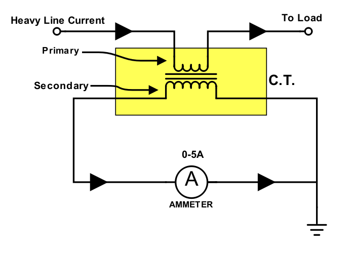
Current Transformer (CT) - Construction And Working Principle

14+ Current Transformer Circuit Diagram | Robhosking Diagram